Numerical Simulation of Detailed Neuron Models
Neurons are very complex structures of the human body that govern behaviour, pain, feelings, motion, and most factors that affect human life. The human brain has approximately \(8.6 \times 10^{10}\) neurons, connected by \(1.5 \times 10^{14}\) synapses. For the sake of comparison, the larva of the sea squirt Ciona intestinalis has 231 neurons, mice have approximately \(71\) million neurons, and the African elephant has almost three times as many neurons as humans, with \(25.7 \times 10^{10}\) neurons. The Wikipedia entry List of animals by number of neurons gives a longer list of neuron counts per animal.
The brain can be studied at many scales, as illustrated in the picture below. At the largest scale, the brain is divided into regions, each with a different role (a), and each region is made of many neurons. A neuron is a cell with a body, many branched dendrites that receive signals, and a long axon that sends signals to other neurons (b). Neurons pass signals to each other through synapses, where chemical messengers cross a small gap between two cells (c).
At the smallest scale, ion channels in the neuron’s membrane let sodium and potassium ions flow in and out of the cell. This flow of ions changes the voltage across the membrane, and creates the neuron’s electrical signal (d).
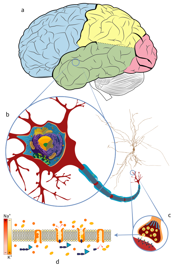
The scales of the brain: (a) brain regions, (b) neuron, (c) synapse, and (d) ion channels in the neuron membrane. Adapted from: Mariana Villarreal (LadyofHats), Wikimedia Commons; and Blausen.com staff, Medical gallery of Blausen Medical 2014, WikiJournal of Medicine
Due to the very sophisticated anatomical structure and behaviour of neurons, numerical methods are used to approximate neuron models and simulate the electrical activity of neural networks. This post focuses on the electrical activity at the level of the neuron: how the flow of ions changes the membrane voltage, and how it is simulated with the numerical methods of the NEURON simulator.
Levels of Detail in Brain Simulation
Brain simulators also work at different levels of detail, as displayed in the picture below, where each model zooms into a part of the model on its left:
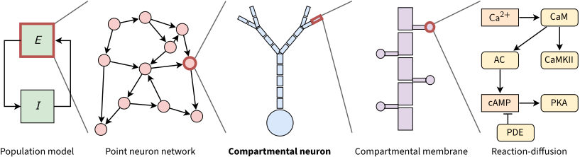
Levels of detail in brain simulation. Each red outline marks the part that the next model describes in more detail. This post covers the compartmental neuron model (in bold). In the reaction-diffusion model, the line with a flat head marks the breakdown of cAMP by PDE. Adapted from: J. M. Eppler, Introduction to NEST, First community workshop on NESTML, 2015
- Population models describe the average activity of large groups of neurons. A simple example is one excitatory population (\(E\)) and one inhibitory population (\(I\)) that drive each other, as in the Wilson–Cowan model.
- Point neuron networks model each neuron as a single point, with no shape. The simplest example is the Leaky Integrate-and-Fire (LIF) model (1907), which has no ion channels: it treats the membrane as an RC circuit, and the neuron spikes when its voltage reaches a threshold.
- Compartmental neuron models keep the branched shape of the neuron, and split the dendrites and the axon into small compartments, each with its own voltage and its own ion channels. This is the model used in the rest of this post.
- Compartmental membrane models describe small parts of the membrane in more detail, such as the dendritic spines that receive synapses.
- Reaction-diffusion models describe the chemical reactions inside the cell, and how molecules such as calcium spread through it.
Most simulators support only point neurons, with LIF or simple Hodgkin-Huxley dynamics. These models run the same few equations on every neuron, and are therefore well suited to vector (SIMD) architectures. Compartmental models are harder to simulate, as each neuron is a tree of compartments with many types of ion channels, and each compartment depends on its neighbors. In practice, point neurons are used to simulate large networks, and compartmental models when the morphology and the ion channels of each neuron matter.
Hodgkin-Huxley Model and Cable Theory
The Hodgkin-Huxley (HH) model (A. L. Hodgkin and A. F. Huxley, 1952), derived from measurements on the giant axon of the squid, is built on several assumptions that disregard various features of the living cell. It reduces the multidimensional complexity of the propagation and interaction of electrical signals in spatially extended nerve cells to a set of one-dimensional constraints. These constraints fit the Cable Theory, a mathematical model that describes the changes in electric current and voltage along passive neurites.
A neuron’s membrane is formed by a phospholipid bilayer, a dielectric material that acts as a leaky capacitor. The cytoplasm inside the neurite (a part of a dendrite or axon) is considered to be an excellent ohmic conductor, and the voltage within its membrane is assumed to be constant over each cross-section. The neurites are considered to be long and thin, so that the voltage is assumed to vary much more along the long axis of the neural process than perpendicular to it. Therefore, the diffusion of ions along the membrane surface and the dynamics of current perpendicular to the membrane inside the neurite are deemed irrelevant.
The neuron morphology is simplified to a branched tree of interconnected neurites, each short enough to accept that the voltage across it is constant. External to the neuron’s morphology, certain mechanisms lead to electrical and chemical reactions that affect the potential of each individual capacitor. These mechanisms are typically gating channels, and allow the in/outflux of molecules (ions) that depolarize or hyperpolarize the membrane accordingly.
Other important mechanisms are the synapses, which represent the interneural connections of the circuit. Synapses can drive the post-synaptic membrane potential upwards or downwards based on the excitatory or inhibitory properties of the pre-synaptic cell. Spikes are initiated when the potential of a membrane hits a particular Action Potential (AP) threshold, and are characterized by a stiff change of membrane potential.
The lowest AP threshold on a neuron is typically at the beginning of the axon (the Axon Initial Segment), where spikes are first initiated. Other APs may happen throughout the axonal arborization as a current propagation mechanism. Spikes are driven by a fast influx of Sodium (\(Na^+\)) ions, and by the slow outflux of Potassium (\(K^+\)) ions. The chloride (\(Cl^-\)) conductance helps to bring the membrane potential back to the rest state following an activation.
Several other mechanisms, such as gap junctions (electrical synapses), extracellular space mechanisms, or second messengers, also exist. In the cable approximation model, the complexity of these mechanisms is reduced to the measurement of their ionic conductance. When the conductance of these molecules is constant, it is called a leak (passive) conductance. A compartment in ionic equilibrium, i.e. where the influx and outflux of ions cause no variation of its potential, is said to be at its reversal potential.
Once a stimulus brings the membrane potential above the threshold, the potential rises steeply, then falls below its resting value, before it returns to rest. This voltage trajectory of a spike is illustrated in the following picture:
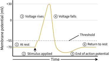
The voltage trajectory during an action potential (spike). Adapted from: OpenStax, Anatomy and Physiology, Fig. 12.24
Mathematical Basis
The application of cable theory to the calculation of electrical signaling throughout neurons reduces the activity of a neuron compartment to a second-order partial differential equation that governs the change of axial current with time and distance. It models the relationship between current and voltage as a one-dimensional cable, described by the cable equation:
\[\frac{\partial V}{\partial T} + F(V) = \frac{\partial^2 V}{\partial X^2}. \label{equation338_neuronbook}\]Here, \(V\) is the membrane potential, \(F(V)\) the ionic current term, and \(T\) and \(X\) the time and the distance along the cable, scaled by the time and space constants defined at the end of this section.
Because the cable equation is linear and homogeneous for a passive membrane (where the ionic current term is \(F(V) = V\)), it obeys the superposition principle. The superposition principle states that, for all linear systems, the net response at a given place and time caused by several stimuli equals the sum of the responses to each stimulus individually. More general solutions suitable for branched neurons can be obtained by summing equations of this form, with an appropriate boundary condition.
Neurons are represented as interconnected neurites with individual properties, later discretized in time and space to allow for a conversion into algebraic difference equations, which can be solved iteratively using numerical methods. For any given neurite, the principle of conservation of charge requires that the sum of currents from all sources must equal 0. The charge conservation principle states that electric charge can neither be created nor destroyed, and that the net quantity of electric charge, given by the sum of positive and negative charges, is always conserved, i.e.
\[\sum i_a - \int_A i_m dA = 0\]where \(i_a\) is the axial current [mA] flowing through the compartment’s region, and \(\int_A i_m dA\) is the integral of the transmembrane current density \(i_m\) [mA/cm\(^2\)] over the membrane area \(A\) [cm\(^2\)]. This concept is illustrated in the following picture:
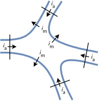
The net current entering a region, bounded by the membrane (blue) and the thin black lines, is zero: the axial currents \(i_a\) balance the membrane current \(i_m\). Adapted from: Hines and Carnevale (1997), The NEURON simulation environment, Fig. 3.1
A common assumption is that a neuron is spatially divided into small compartments, at most \(40 \, \mu m\) long in the cell models of the Blue Brain Project. The spatially varying \(i_m\) in any compartment \(j\) is then well approximated by its value at the center, therefore
\[\int_A i_{m_j} dA_j = i_{m_j} A_j = \sum_k i_{a_{kj}}\]Ohm’s law states that the current between two points of a conductor is directly proportional to the voltage across those two points, as described by the relationship \(I = V / R\). The axial current between a compartment \(j\) and its neighbors is calculated with Ohm’s law. Each axial current \(i_a\) is approximated by the voltage drop between the centers of the compartments divided by the resistance of the path between them (the axial resistance), therefore:
\[i_{a_{kj}} = \frac{v_k - v_j}{r_{jk}}\]where \(r_{jk}\) is the axial resistance between the compartments \(k\) and \(j\). Finally, the total membrane current, given by the sum of the capacitive and ionic components, must equal the sum of the axial currents \(i_{a_{kj}}\) that enter the compartment \(j\) from each adjacent neighbor \(k\), thus:
\[c_j \frac{dv_j}{dt}+i_{ion_j} (v_j, t) = i_{m_j}A_j \label{convervation_energy_eq}\]where \(c_j\) is the membrane capacitance of the compartment, \(c_j (dv_j / dt)\) the capacitive component, and \(i_{ion_j} (v_j, t)\) represents the current through the ion channels’ conductances. Applying spatial discretization to the equation of conservation of charge leads to a set of ordinary differential equations of the form:
\[c_j \frac{dv_j}{dt}+i_{ion_j} (v_j, t) = \sum_k \frac{v_k - v_j}{r_{jk}}. \label{equation345_neuronbook}\]Equation \ref{equation345_neuronbook} omits any injected source currents, which (if present) are included on its right-hand side. In the special case of an unbranched cable with constant parameters, the axial current is delimited by two points involving compartments \(j-1\) and \(j+1\), i.e.
\[c_j \frac{dv_j}{dt}+i_{ion_j} (v_j, t) = \frac{v_{j-1} - v_j}{r_{j-1,j}} + \frac{v_{j+1} - v_j}{r_{j+1,j}} \label{equation346_neuronbook}\]For a compartment with length \(\Delta x\) and diameter \(d\), the capacitance is given by \(C_m \pi d \Delta x\) and the axial resistance by \(R_a \frac{\Delta x}{\pi (d/2)^2}\), where \(C_m\) is the specific membrane capacitance and \(R_a\) the cytoplasmic resistivity. Replacing those terms in equation \ref{equation346_neuronbook}, and dividing both sides by the membrane area \(\pi d \Delta x\) of the compartment (so that \(i_{ion_j}\) becomes a current density), leads to:
\[C_m \frac{dv_j}{dt}+i_{ion_j} (v_j, t) = \frac{d}{4R_a} \frac{v_{j+1} - 2 v_j + v_{j-1}}{ \Delta x^2} \label{equation347_neuronbook}\]If the discretization variable is assumed to be small enough, i.e. \(\Delta x \rightarrow 0\), using finite differences the first derivative at the point \(j\) is given by \(\frac{v_j - v_{j-1}}{\Delta x}\) and \(\frac{v_{j+1} - v_j}{\Delta x}\), and the second-order correct approximation of the second derivative by
\[\frac{\partial^2v}{\partial x^2} = \left( \frac{v_{j+1} - v_j}{\Delta x} - \frac{v_j - v_{j-1}}{\Delta x} \right) \frac{1}{\Delta x} = \frac {v_{j+1} - 2v_j + v_{j-1}}{ \Delta x^2} \label{eq_2nd_order_finite_difference}\]and this term can be replaced in equation \ref{equation347_neuronbook} to get
\[C_m \frac{dv_j}{dt}+i_{ion_j} (v_j, t) = \frac{d}{4R_a} \frac{\partial^2v}{\partial x^2} \label{equation348_neuronbook}\]Following Ohm’s law, making the substitution \(i = v / R_m\) for the ionic current of a passive membrane (where \(R_m\) is the specific membrane resistance, and \(v\) is measured from the resting potential) and multiplying both sides by \(R_m\) leads to the formulation
\[R_m C_m \frac{dv_j}{dt} + v = \frac{d R_m}{4R_a} \frac{\partial^2v}{\partial x^2} \label{equation349_neuronbook}\]By substituting \(t = T \tau\) and \(x = X \lambda\), equation \ref{equation349_neuronbook} is scaled to the time constant \(\tau = R_m C_m\) and the space constant (or length constant) \(\lambda = (1/2) \sqrt{d R_m / R_a}\), leading to the final formulation in the form of the Cable equation \ref{equation338_neuronbook}.
Ionic Currents
All channels may be characterized by their resistance or by their conductance \(g = 1/R\), and by gating variables that describe the open probability of a given channel, generalizing external events that may block an ion channel. Hodgkin and Huxley formulated the ionic components of a membrane as:
\[\sum_k I_k = g_{Na} m^3 h (v - E_{Na}) + g_K n^4 (v - E_K) + g_L (v - E_L)\]where \(v\) is the membrane potential, \(E\) represents the reversal potentials and \(m\), \(n\) and \(h\) the gating variables (see the original HH paper for details of the individual ODEs and reported values). The leak generalizes any other voltage-independent conductance and is represented by \(L\).
The HH model has only sodium, potassium and leak channels, and needs four equations: one for the voltage, and one for each gating variable \(m\), \(n\) and \(h\). Since 1952, the zoo of known ion channels has grown a lot (see Channelpedia for a list of ion channel models). In general, the current through the membrane of a compartment \(j\) with voltage \(v_j\) is given by:
\[I = C \frac{dv_j}{dt} + \sum_i g_i w_i (v_j - E_i)\]where each channel type \(i\) has a maximum conductance \(g_i\), a gating term \(w_i\) (such as \(m^3 h\) for sodium) and a reversal potential \(E_i\). This equation describes the electrical circuit in the picture below, where the membrane is a capacitor and each ion channel type is a resistor in series with a battery, whose voltage is the reversal potential of that ion.
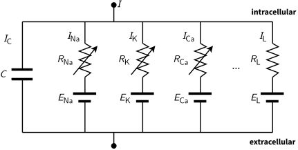
The electrical circuit of one compartment. The membrane is the capacitor \(C\). Each ion channel is a resistor \(R\) in series with a battery \(E\), its reversal potential. Arrows mark gated channels, whose resistance changes over time. The leak \(L\) has a constant resistance. \(I\) is the total current through the membrane
Reversal Potential
The reversal potential for a particular ion flux in a compartment is given by the Nernst equation
\[E = \frac{RT}{zF} \ln \frac{\text{[ion]}_{out}}{\text{[ion]}_{in}} \approx \frac{RT}{zF} 2.3026 \log _{10} \frac{\text{[ion]}_{out}}{\text{[ion]}_{in}}\]where \(\text{[ion]}_{out}\) and \(\text{[ion]}_{in}\) denote the ionic concentration on the outside and inside of the cell, \(T\) is the temperature in Kelvin (assumed to be \(307.15 K\), or \(34 ^{\circ}\mathrm{C}\)) and \(z\) is the charge of the ion. \(R\) and \(F\) are the gas (\(8.3144621 J\) \(K^{-1}\) \(mol^{-1}\)) and Faraday (\(96485.33289(59)\) \(C\) \(mol^{-1}\)) constants, respectively. The typical reversal potentials for the most common ions are approximately:
- \(E_{Cl^-}=-84 mV\) with \([Cl^-]_{in}=5 mM\) and \([Cl^-]_{out}=120 mM\);
- \(E_{K^+}=-96 mV\) with \([K^+]_{in}=150 mM\) and \([K^+]_{out}=4 mM\);
- \(E_{Na^+}=66 mV\) with \([Na^+]_{in}=12 mM\) and \([Na^+]_{out}=145 mM\); and
- \(E_{Ca^{2+}}=122 mV\) with \([Ca^{2+}]_{in}=0.1 \mu M\) and \([Ca^{2+}]_{out}=1 mM\).
The reversal potential of a typical HH compartment with \(Na^+\), \(K^+\) and \(Cl^-\) ion channels, i.e. its resting membrane potential, is given by the Goldman–Hodgkin–Katz voltage equation as:
\[V = \frac{RT}{F} \ln \frac{P_{Na} [Na^+]_{out} + P_{K} [K^+]_{out} + P_{Cl} [Cl^-]_{in}} {P_{Na} [Na^+]_{in} + P_{K} [K^+]_{in} + P_{Cl} [Cl^-]_{out}}\]where \(P_{Na}\), \(P_{K}\) and \(P_{Cl}\) are the permeabilities of the membrane to each ion. With the concentrations above and the permeability ratio \(P_K : P_{Na} : P_{Cl} = 1 : 0.04 : 0.45\) of the resting squid giant axon (Hodgkin and Katz, 1949), the resting potential is about \(-75 mV\).
Boundary Conditions
A neurite with a free ending point follows a Neumann boundary condition (which specifies the value of the normal derivative of the function at the boundary) of the form \(\frac{\partial v}{\partial x}=0\), i.e. no current flows through the terminal of a cable.
Branching Points
Branching points are modeled as idealized portions of the neurite that do not have membrane properties yet have axial current. Spatial discretization is equivalent to reducing the spatially distributed neuron to a set of connected compartments, and results in a set of ordinary differential equations that respect Kirchhoff’s current law. Kirchhoff’s current law, based on the principle of conservation of electric charge, states that the sum of currents entering any junction is equal to the sum of currents leaving that junction.
In a branched tree, every compartment \(j\) except the root has one parent \(p_j\) and zero or more children \(k\). The sum over the neighbors \(k\) in equation \ref{equation345_neuronbook} then splits into one term for the parent and one term per child:
\[c_j \frac{dv_j}{dt}+i_{ion_j} (v_j, t) = \frac{v_{p_j} - v_j}{r_j} + \sum_{k \, : \, p_k=j} \frac{v_k - v_j}{r_k}\]where \(r_j\) is the axial resistance between compartment \(j\) and its parent. The Hines solver below relies on this parent-child structure.
Numerical Resolution Methods in NEURON
Most equations that govern brain mechanisms do not have an analytic solution. The NEURON simulator (henceforth referred to as NEURON) addresses such problems by allowing for biologically realistic (not infinitely detailed) models of brain mechanisms, using several methods for an accurate discretization of the neuronal activity.
The Hines Solver
Due to the unique morphology of a cable model representation of a discretized neuron, NEURON implements an optimized linear solver for bifurcated trees, called the Hines Algorithm (Efficient computation of branched nerve equations, Hines, Elsevier, 1984). Data is represented as a sparse matrix (tridiagonal, except for the entries of the branching points) where the indices of the parent nodes (the ones immediately above in the tree structure) are provided by an extra vector \(p\).
The coefficient of the membrane potential of each compartment in its own equation is represented by the main diagonal. The contributions from a parent to its children compartments (and vice versa) are represented by all cells on the same row (column) of the upper (lower) triangle of the matrix. As each compartment can have only one parent, this enforces only one cell per row on the lower triangle, and one cell per column on the upper triangle. For completeness, the following pictures present a neuron’s dendritic arborization spatially discretized based on the cable model (left) and its sparse matrix representation according to the Hines algorithm (right).
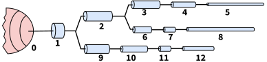
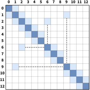
In the pictures above, compartments 6 and 9 start new branches, so the entries that link them to their parents, 2 and 1, lie outside the three diagonals of the matrix (joined to the diagonal by dashed lines).
The main rationale behind the Hines algorithm is that the compartments can be numbered sequentially, so that each one has an index greater than its parent’s. The computational complexity of the solver is then reduced from the \(O(n^3)\) of a typical Gaussian elimination to \(O(n)\). Given a tridiagonal matrix with vectors \(D\) (main diagonal), \(b\) (lower diagonal) and \(a\) (upper diagonal), representing a single cable without branching, it can be shown that the Hines algorithm is an inverted Gaussian elimination adapted for branched structures:
- Starting with the forward triangulation process on each \(cell_i\) on row \(i\):
- \(cell_i \leftarrow cell_i - \frac{b_i}{D_{i-1}} row_{i-1}\);
- Changing the function variable from \(i\) to \(i+1\):
- \(cell_{i+1} \leftarrow cell_{i+1} - \frac{b_{i+1}}{D_i} row_i\);
- Replacing forward by backward triangulation:
- \(cell_{i-1} \leftarrow cell_{i-1} - \frac{a_{i-1}}{D_i} row_i\);
- Indexing each off-diagonal element by its child node, so that \(a_i\) is the element on row \(i-1\) and column \(i\) (the top node has no parent, so \(a_0\) and \(b_0\) are not used):
- \(cell_{i-1} \leftarrow cell_{i-1} - \frac{a_i}{D_i} row_i\);
- Changing parents’ indices from a single cable (\(i-1\)) to a branched tree structure (\(p_i\)):
- \(cell_{p_i} \leftarrow cell_{p_i} - \frac{a_i}{D_i} row_i\);
which is the backward triangulation applied by Hines. The substitution step in Hines is, in turn, replaced by a forward substitution.
An important feature of the Hines algorithm is that it allows parallelization at the junction level. By starting the computation at the branches without children (terminal branches), the individual contributions from children branches can be computed in parallel and included recursively at the parent compartment’s node.
Mechanisms and Events
In NEURON, extra-cellular activity, recording patches, voltage clamps, interneuron kinetics (such as synapses and gap junctions) or any other contribution that affects the membrane potential itself are introduced as mechanisms. An input delivered to a mechanism at a specific time, such as the arrival of a spike at a synapse, is called an event. Events in NEURON are managed by the event delivery system (Efficient discrete event simulation of spiking neurons in NEURON, Carnevale and Hines, ResearchGate). Mechanisms are encoded in the NMODL language (Expanding NEURON’s Repertoire of Mechanisms with NMODL, Hines and Carnevale), where the main user-provided blocks are:
- BREAKPOINT: the main computation block of the model, where states are integrated by a SOLVE statement;
- DERIVATIVE: if states are governed by differential equations, assigns values to the derivatives;
- PROCEDURE and FUNCTION: function declaration and calls;
- PARAMETER and CONSTANT: read-write and read-only variables, respectively;
- NET_RECEIVE: the actions taken when the mechanism receives an event, e.g. a synaptic input.
Fixed Time Step Integration
As shown previously, the principle of conservation of charge between two or more coupled compartments, including an external source of current injection \(I_{inj}\), can be stated by a set of equations of the form:
\[c_j \frac{dv_j}{dt}+i_{ion_j} (v_j, t) = \sum_k \frac{v_k - v_j}{r_{jk}} + I_{inj} \label{equation42_neuronbook}\]The numerical resolution of the aforementioned equations raises several concerns about stability, accuracy and efficiency, caused by the errors of the spatial discretization of the cable theory model and by the algorithms used to solve it numerically. This has been analyzed in The NEURON book, where the authors compare its numerical accuracy against the spatial discretization of the Fourier cosine terms \(\cos ( \pi n x / L)\) of a cable of length \(L\).
NEURON performs a spatial discretization of a cable by placing \(m\) points at the centers of equidistant intervals of size \(\Delta x = L/m\), thus each point is placed at \(x = (i+0.5) L/m\), for \(0 \leq i < m\). This is known (from numerical methods theory) to have higher accuracy than the traditional method, which places the \(m\) points at positions \(x = i \,\, L/(m-1)\) for \(0 \leq i \leq (m-1)\). In either case, \(m\) points are placed in a given cable, and \(m=1\) corresponds to a spatial frequency of \(0\), i.e. a uniform membrane potential along the entire cable.
Also, the highest number of half waves that can be represented by the discretized system is \(n = m-1\), which is valid according to the Nyquist–Shannon sampling theorem. The Nyquist–Shannon sampling theorem establishes a condition for a sampling rate sufficient for a discrete sequence of samples (digital information) to capture all the information from a continuous-time signal of finite bandwidth (analog information). In practice, it states that more than two samples must be captured per cycle to measure the frequency of a signal.
The resolution of a spatially discretized cable with respect to time follows the standard equation of a linear passive capacitor. The voltage \(V\) of a capacitor at a given instant \(t\) is given by \(V = V_0 e^{-t / \tau}\), where the time constant is \(\tau = RC\), and \(V_0\), \(R\) and \(C\) denote the initial voltage and the circuit’s resistance and capacitance, respectively. For each spatial frequency of the discretized cable, this equation takes the form:
\[\frac{dV_{nm}}{dt} = -k_{nm} V_{nm} \label{eq_310_neuronbook}\]whose analytic solution is
\[V_{nm} = V_{0_{nm}} e^{-k_{nm}t}\]where \(V_{nm}\) is the amplitude of the spatial frequency \(n\) (the number of half waves) for \(m\) points per cable, and the rate constant \(k_{nm}\) is obtained by discretizing equation \ref{equation349_neuronbook} at the \(m\) points:
\[k_{nm} = \frac{1}{\tau_m} \left( 1 + \left( \frac{2 m \lambda}{L} \right)^2 \sin^2 \frac{n \pi}{2m} \right)\]where \(\tau _m = c/g\) is the membrane time constant. For \(n=0\) (uniform potential), the rate constant is the inverse of the membrane time constant, \(k_{nm} = 1/\tau_m\). The temporal discretization of a fixed time step approach follows the basic approximation principle for stepping between two time instants:
\[\frac{d V}{d t} \approx \frac{V(t + \Delta t) - V(t)}{ \Delta t}\]Fixed time step integration is typically performed with either the Euler or the Crank-Nicolson method. The explicit Forward Euler provides first-order accuracy, and its time step must never be more than twice the smallest time constant in the system. As a reminder, a numerical solution to a differential equation is said to be of \(p^{th}\)-order if the error \(\varepsilon\) is proportional to the \(p^{th}\) power of the step size \(\Delta t\): \(\varepsilon(\Delta t) = K \Delta t^p\).
The gap between the analytic and the numerical solutions is particularly large when the system’s voltage is changing rapidly, making it unstable. This has been described in detail in The NEURON book, for two coupled compartments with time constants of 1 s and 1/41 s. With a time step of \(\Delta t = 0.001 s\), the numerical solution comes close to the analytic one, but a step of 0.2 s, chosen to follow the slow decay at a lower cost, makes the solution unstable. Therefore, in such stiff systems, which mix fast and slow time constants, Forward Euler needs a small time step during the whole simulation, at the cost of a very high computational load, and is not applied in NEURON.
The Backward Euler method computes the solution of a set of nonlinear simultaneous equations at each step, therefore requiring a step size as large as possible to compensate for the extra work. For reasonable values of \(\Delta t\), it produces fast simulations that are generally correct, explained by the fact that tightly coupled compartments do not generate large error oscillations and approach the system’s equilibrium quickly. As its numerical error is proportional to \(\Delta t\) anyway, the Backward Euler in NEURON does not resort to iterations to deal with non-linearities.
A function or map \(f(x)\) is said to be linear if it satisfies the properties of superposition (\(f(x+y) = f(x) + f(y)\)) and homogeneity (\(f (\alpha x) = \alpha f (x)\)). The equation(s) of a non-linear system cannot be written as a linear combination of its unknown variables or functions.
The accuracy of the Backward Euler is improved by the Crank-Nicolson method, which provides an error proportional to the square of the step size. As \(\Delta t\) becomes large, the solution oscillates with decreasing amplitude, making it numerically stable (see Hines and Carnevale, 1997 for a numerical resolution of passive compartments and action potentials). Computation-wise, the Crank-Nicolson method is stable and more accurate than the Backward Euler, while requiring the same number of computation steps as Backward Euler. This can be shown as follows: for a linear system \(dy/dt = Jy\), take implicit (Backward) Euler to be defined as
\[y^{n+1}= y^n + \Delta t \,\, J y^{n+1} = (I - \Delta t \,\, J)^{-1} y^n\]and explicit (Forward) Euler as:
\[y^{n+1} = y^n + \Delta t \,\, J y^n = (I + \Delta t \,\, J) y^n\]then Crank-Nicolson can be described as:
\[y^{n+1} = y^n + \frac{1}{2}\Delta t \space{ } J y^{n+1} + \frac{1}{2}\Delta t \space{ } J y^{n} = \left( I - \frac{1}{2} \Delta t \,\, J \right)^{-1} \left(I + \frac{1}{2} \Delta t \,\, J \right) y^n\]which is one step of implicit Euler with half the step size, \(y^{n+1/2} = (I - \frac{1}{2} \Delta t \,\, J)^{-1} y^n\), followed by a linear extrapolation, therefore requiring no extra computation for the added accuracy:
\[y^{n+1} = 2 y^{n+1/2} - y^n = \left(2 \left(I - \frac{1}{2} \Delta t \,\, J \right)^{-1} - I \right) y^n = \left(I - \frac{1}{2} \Delta t \,\, J \right)^{-1} \left(I + \frac{1}{2} \Delta t \,\, J \right) y^n \label{eq_crank_nicholson_steps}\]In NEURON, the Backward Euler is the default method, as it is very stable, and the Crank-Nicolson method is an option for second-order accuracy, with a time step small enough to avoid large error oscillations.
Computational Implementation
NEURON’s workflow for the resolution based on interleaved time stepping is defined by a set of iterations that run sequentially for every computation and communication time step, of duration \(\Delta t\) and \(\Delta t_{comm}\) respectively:
- at instant \(t\):
- delivery of all (queued) spikes for the subsequent iteration;
- channels run their mechanisms to deliver current;
- synaptic currents are delivered to the compartments;
- at instant \(t + \Delta t /2\):
- Linear algebra resolution via the (Hines) solver;
- at instant \(t + \Delta t\):
- Update channel states;
- Update synapse states;
- Action Potential threshold detection;
- if \(t\) is a multiple of \(\Delta t_{comm}\):
- Perform a collective call to send/recv spikes;
- Place all received spikes in the spike queue;
- Jump to next time step: \(t \leftarrow t + \Delta t\);
\(\Delta t\) is defined by the fastest mechanisms requiring no data exchange between compute nodes (normally the fastest \(Na^+\) channels). \(\Delta t_{comm}\) is defined by the fastest mechanism requiring communication among compute nodes, typically the minimal synaptic delay across all synapses, or (when applicable) the update frequency of extra-cellular mechanisms or gap junctions.
NEURON’s implementation of fixed time step integrates the equation over the \(\Delta t\) step by calling all the BREAKPOINT blocks of the models at \(t + \Delta t /2\) twice, with \(v\) and \(v+.001\). This computes the current and conductance contributions of each mechanism, and forms the matrix conductance × voltage = current. The matrix is then solved for \(v(t+ \Delta t)\). Lastly, in line with the staggered time stepping scheme, the SOLVE statement of the models (within the BREAKPOINT block) is executed with \(t+ \Delta t\) and the new \(v\) to integrate those states, from the new \(t-\Delta t/2\) to the new \(t+\Delta t/2\).
A strong argument supporting a fixed time step approach is the possibility of data vectorization. At every time step, several instances of the same mechanism run the same operations with different inputs, therefore allowing for a data layout in memory that takes advantage of the vectorization (SIMD) units of modern architectures.
Handling of non-linearity
Although nonlinear equations generally require an iterative resolution to maintain second-order correctness, the HH membrane properties allow the cable equation to be described linearly and solved without iterations, while keeping second-order accuracy. NEURON’s variant of Crank-Nicolson with staggered time stepping applies the Strang splitting method to calculate the values of the compartment voltage and Hodgkin-Huxley gating states on interleaved time intervals (Error Analysis and Quantification in NEURON Simulations, Casalegno et al., 2016). Therefore, it converts a large non-linear system into two linear systems, and the problem now has second-order accuracy, with a computation cost almost identical to the Backward Euler method.
As a side note, a direct solution of the voltage equation using a linearized membrane current \(I(V,t)=g(V-E)\) at a time step \(t \rightarrow t + \Delta t\) is possible. It requires the conductance \(g\) and the reversal potential \(E\) to have second-order accuracy at time \(t+\Delta t/2\), as detailed in The NEURON book.
The conductance of HH-type channels is given by a function of the state variables \(n\) (\(K^+\)), \(m\) and \(h\) (\(Na^+\)). Therefore, this second-order accuracy at \(t+\Delta t/2\) is achieved by performing a calculation with a time step offset of \(\Delta t/2\) from the current voltage time step. In brief, to calculate the second-order accurate integration between \(t-\Delta t/2\) and \(t+\Delta t/2\), only the second-order correct value of voltage-dependent rates at the instant \(t\) is needed.
An important message here is that this resolution as a system of linear equations is only possible for simple models. Neuron models with non-linear state variable ODEs and correlation between states require a fully-implicit resolution, which is possible with Backward Euler with Newton iterations. This is a common use case, and underlies the resolution of extra-cellular mechanisms, capacitors between nodes, and other mechanisms that connect neurons’ evolution over time. For such use cases, the regular Euler and Crank-Nicolson methods described previously have to be used, at the cost of a computationally heavier simulation.
To find more about the topic, The NEURON book explains how to express neuron models in mathematical terms (chapter 3), the numerical methods of NEURON (chapter 4) and how to add new mechanisms with NMODL (chapter 9).